6.6 The Effects View
Effects in the EDGE control console are applied using an effect table, which uses mathematical functions (such as sine or cosine waves) to modify attribute values over time. Each effect appears as a row within the Effects View, where effects can be created and adjusted.
Effects are stored into Playbacks. If a Playback contains multiple cues, effects will track through the Playback just like regular attribute values. When a cue with new effects starts, the EDGE console detects all currently running effects and smoothly crossfades to the new ones. This transition automatically stops any previously running effects on the same attribute. To fully stop an effect on a parameter, an “Off Effect” curve must be applied-this is essentially a flat effect with no size, ensuring the attribute remains static.
Keeping effects in sync is crucial, especially when combining multiple parameters to create a unified motion. For example, in a Fly Out Effect, a fixture’s intensity fades up as the tilt moves upward, then turns off while the tilt moves back down in black. On traditional consoles, separating this effect across two cues-one for tilt and another for intensity-is problematic because the timing may not align. EDGE solves this by automatically synchronizing effects within the same Playback, ensuring they always appear consistent regardless of when Cue 2 is triggered. Additionally, Move in Black can preset effects while maintaining sync. However, effects running in separate Playbacks will not be synchronized.
To open the Effects View, click Home  and select Effects from the top bar.
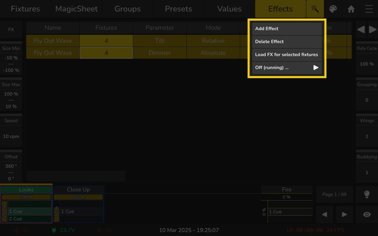
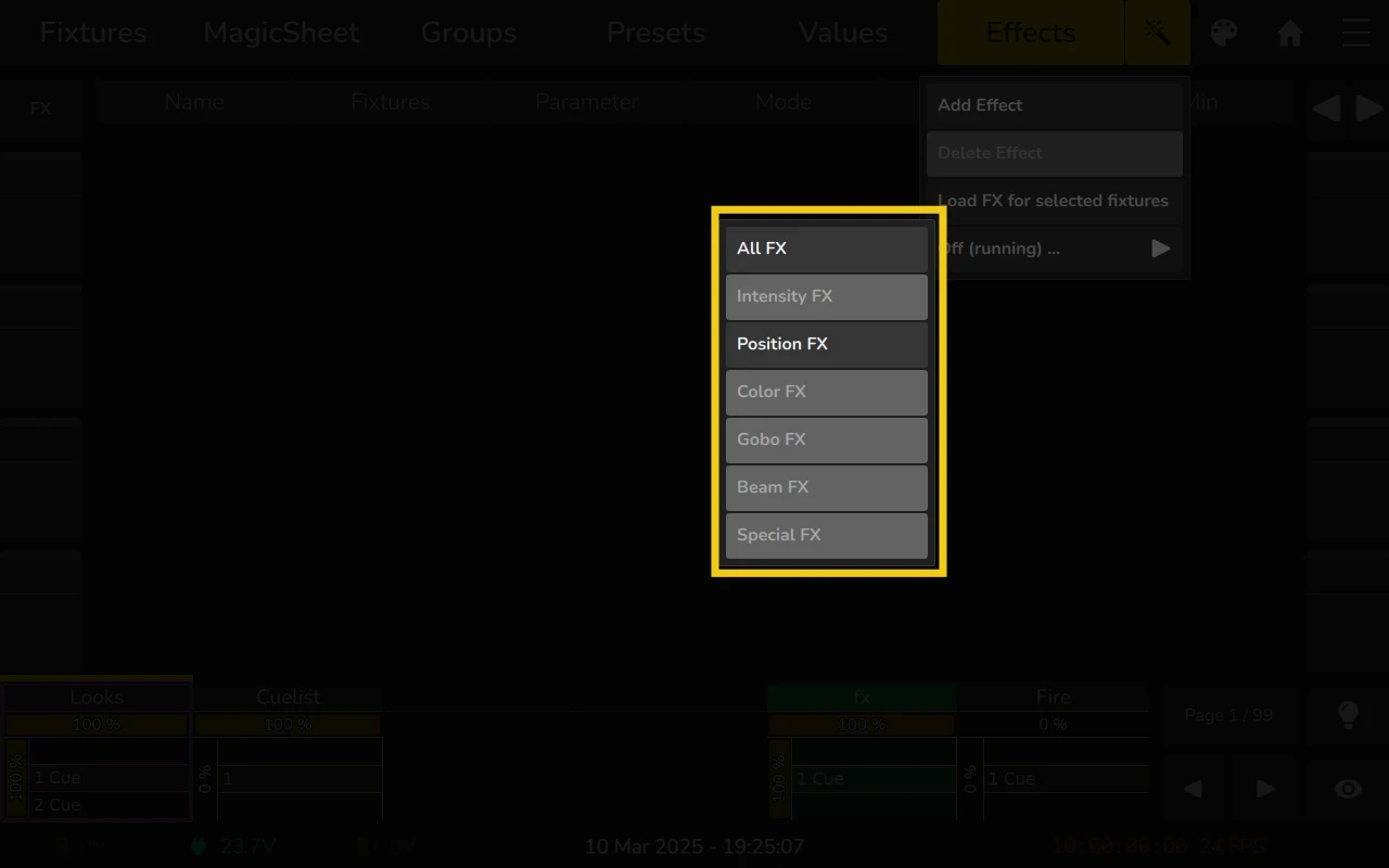
6.6.1 The Effects View Context Menu (Magic Wand Button)
You can access this menu by clicking the Magic Wand  button within the Effects View. The menu provides the following options:
- Add Effect
Adds a new effect to the currently selected fixtures. When selected, a dialog appears prompting you to choose the type of effect. For more details, see Adding Effects. - Delete Effect
Removes the selected effect rows from the Effects View. This action does not stop effects that are currently running in a Playback. - Load FX for Selected Fixtures
Loads all effects currently running in the output for the selected fixtures. - Off (Running)…
A quick-access function that adds Off Effect rows for running effects in Playbacks, specifically for the selected fixtures.
6.6.2 Adding Effects
To add an effect to selected fixtures:
- Select the fixtures you want to apply the effect to.
- Click the Magic Wand button in the Effects View.
- Choose Add Effect.
- Select whether to create a pre-defined, preset or custom effect (see details below).
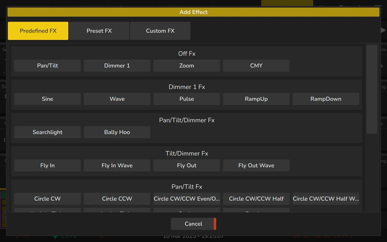
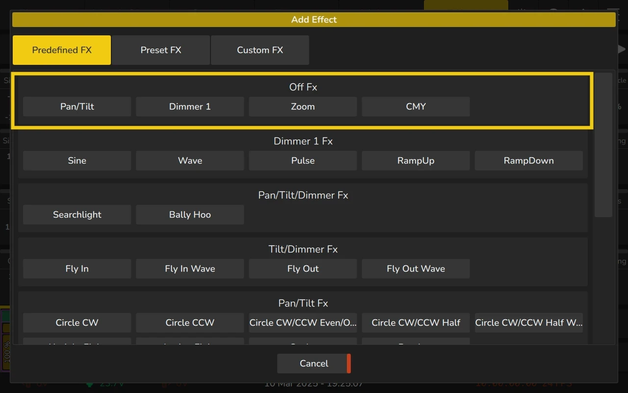
Predefined Effects
Predefined Effects provide a set of ready-made effects with attributes already configured for convenience.
To add a Predefined Effect:
- Follow the steps in Adding an Effect to open the effect selection window.
- Choose Predefined FX.
- Select the desired effect from the list of available presets.
Once added, the effect lines can be further customized in the Effects View to adjust parameters as needed.
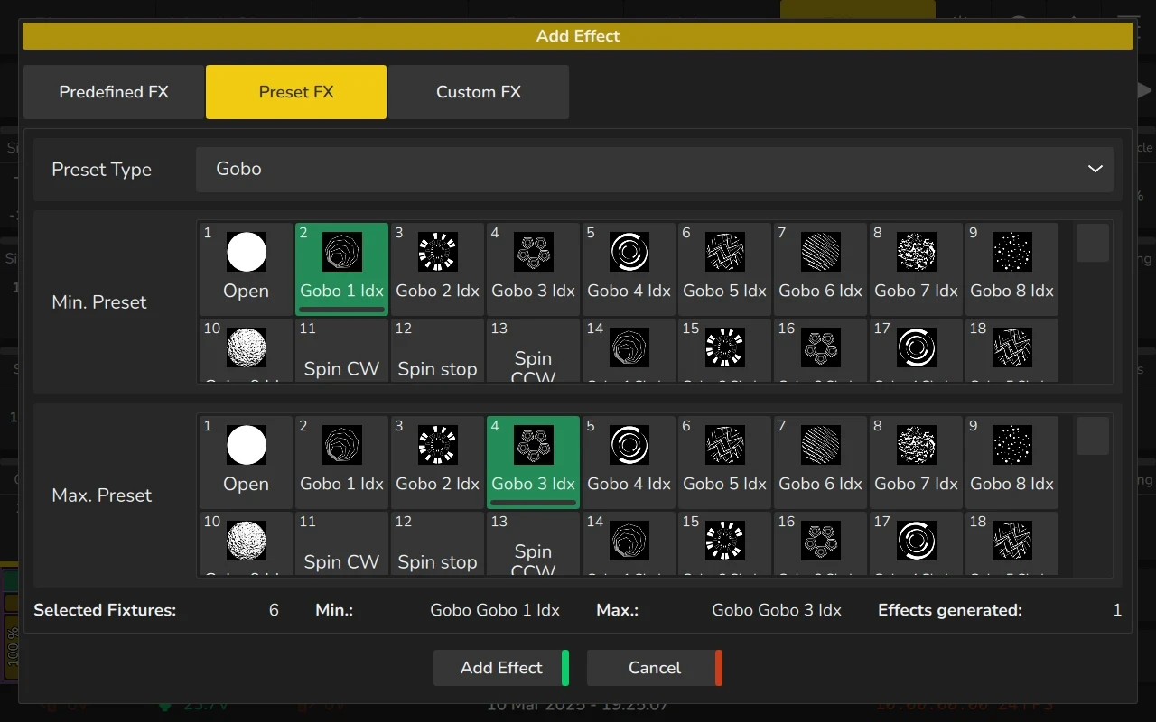
Preset Effects
Preset Effects provide a flexible way to create effects based on presets. This function generates an effect for each attribute that is present in both selected presets. The resulting effect lines are set to Absolute Mode, with the minimum and maximum values determined by the selected presets.
To add a Preset Effect:
- Follow the steps in Adding an Effect to open the effect selection window.
- Select Preset FX.
- Choose the desired Feature Group from the Preset Type list.
- Select a Min. Preset and a Max. Preset.
- Click Add Effect to apply the effect.
Once added, the effect lines can be customized in the Effects View to fine-tune the result.
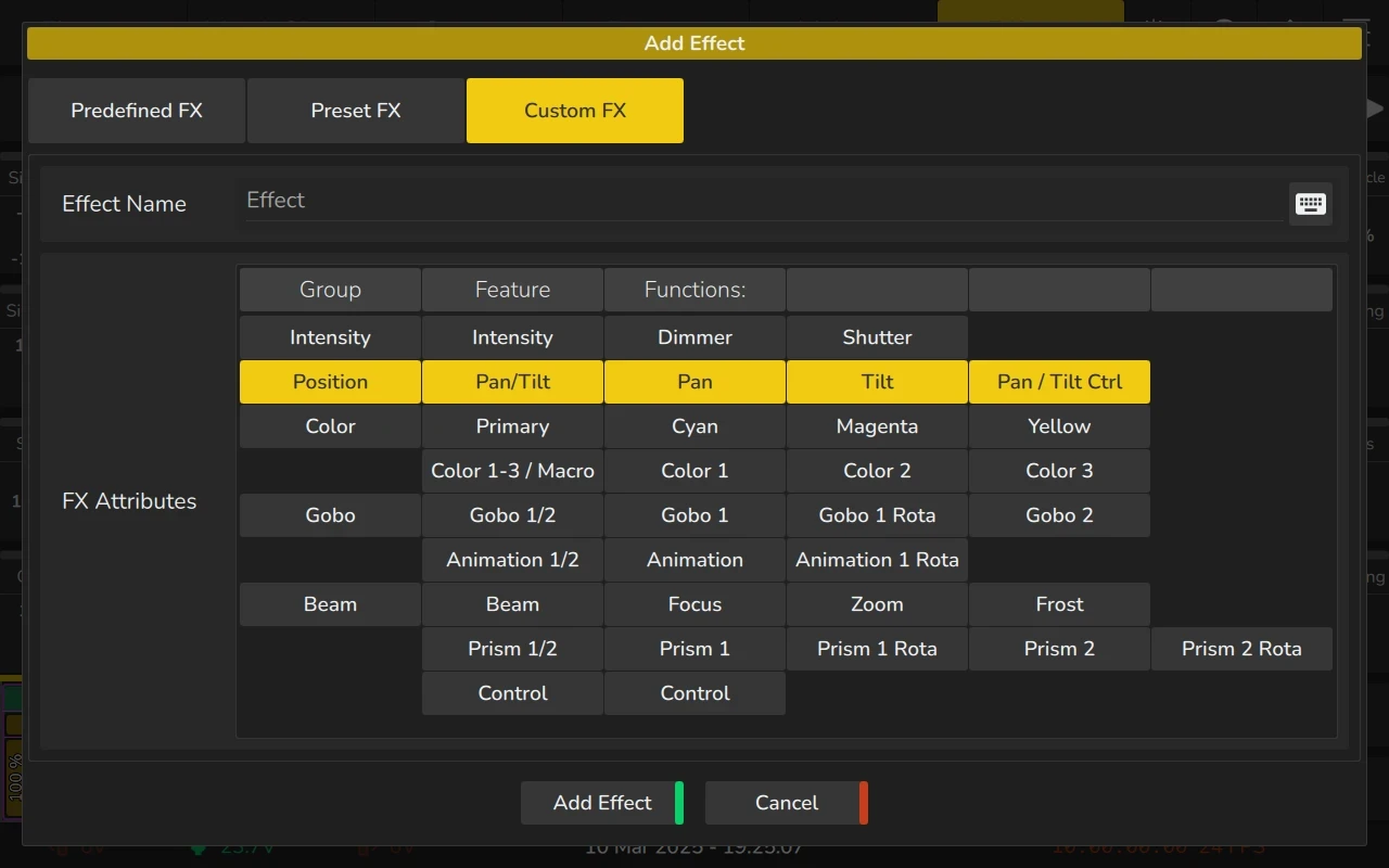
Custom Effects
Custom Effects allow you to create unique effects beyond the predefined options.
To add a Custom Effect:
- Follow the steps in Adding an Effect to open the effect selection window.
- Select Custom FX.
- (Optional) Enter a name for the effect.
- Choose the desired Fixture Functions from the table.
- Click Add Effect to apply the effect.
Once added, the effect lines can be further customized in the Effects View to fine-tune parameters as needed.
6.6.3 Deleting Effects
To delete one or multiple effect rows, they must first be selected.
- Click on any cell within an effect row to select or deselect it.
- Click and drag to select multiple rows at once.
Once selected:
- Click the Magic Wand button.
- Choose Delete Effect from the Action Menu.
- Confirm the deletion in the dialog that appears.
Deleting an effect in the Effects View does not stop the effect if it is already running in a Playback. For example, if you create an effect, record it into Cue 1, then delete the effect and store Cue 2, the effect will still run. To properly stop the effect, add an Off Effect form for the affected parameters in Cue 2, as described below.
6.6.4 Stopping running Effects
To stop one or more effects in a cue, add an effect row for each parameter you want to stop in the editor, with the Off effect type. This can be done at any time, regardless of whether the effect is actively playing back.
If the effect is still visible in the Effects View:
- Simply change the curve type of the appropriate row to Off.
If the effect is not visible in the Effects View:
- Select the fixtures for which you want to stop an effect.
- Click the Magic Wand button in the Effects View.
- Choose **Stop (Running)**from the menu.
- Select whether to apply Off Effects to all parameters or choose specific Feature Groups.
Alternatively, you may also:
- Select the fixtures for which you want to stop an effect.
- Click the Magic Wand button in the Effects View.
- Choose Add FX.
- If the desired parameter appears in the Predefined FX tab under the Off FX section, click on it.
- If it does not appear, select Custom FX, set a name, select the desired Fixture Function, and click Add Effect.
- Once added, change the curve type to Off.
Once this is done, the effect will be stopped in the output.
6.6.4 Modifying Effects
To adjust effect rows in the Effects View:
- Select or deselect effect rows by clicking on any of its cells.
- To select multiple rows, click and drag across the desired rows.
Once effect rows are selected, you can:
- Adjust values using the encoders.
- Double-click or long-press on a cell to open selection lists or keypad dialogs for editing the selected cell’s values.
- Push an Encoder or click an Encoder Label to directly alter its value.
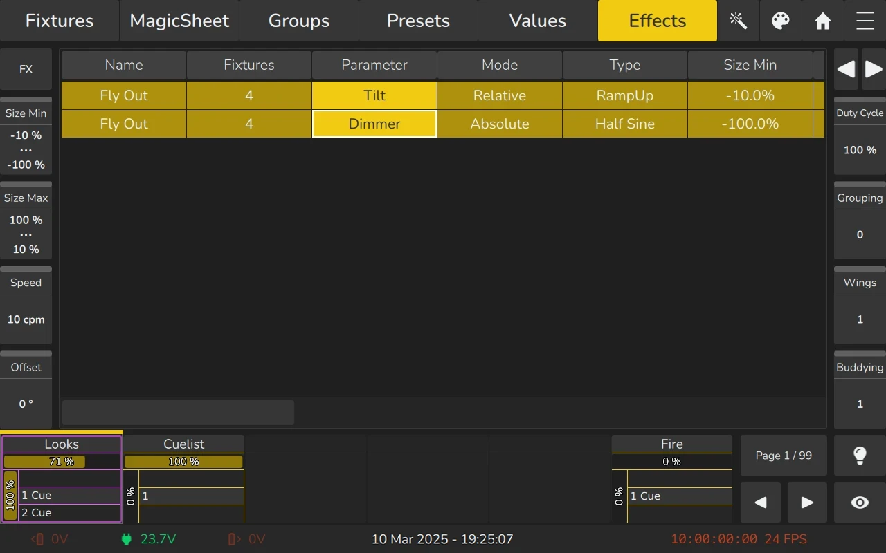
The EDGE console offers a variety of Effect Attributes. More details on these attributes are available further below.
| Column / Attribute | Function |
|---|---|
| Name | Indicates the name of the effect. |
| Fixtures | Indicates the amount of fixtures in each line. Long Press or Double click can be used to select the fixtures from the effect row, or to replace or add fixtures to the effect. |
| Parameter | Indicates the fixture function this effect is running on. |
| Mode | Used to indicate and toggle between “Relative” and “Absolute”. |
| Type | Indicates and sets the effect form for this line.. |
| Size Min | Used to indicate and set the minimum size of the effect. |
| Size Max | Used to indicate and set the maximum size of the effect. |
| Speed | Used to indicate and set the speed of the effect. |
| Offset | Used to indicate and set the offset for each fixture in the effect. |
| Duty Cycle | Used to indicate and set the duty cycle for each fixture in the effect. |
| Grouping | Used to indicate and set the grouping of fixtures in the effect. |
| Buddying | Used to indicate and sets the amount of fixtures which will be treated as one in the effect. |
| Wings | Used to indicate and set the if this effect is mirrored and repeated across multiple fixtures. |
| Invert | Inverts the values of the effect. Behaves the same as reversing Size Min and Size Max. |
| Direction | Used to indicate and set the Direction of the effect. |
| Shots | Used to indicate and set the number of times this effect should be run. |
| Attack | Only available for PWM Effect Form. Softens the slope of the beginning of the PWM Curve. |
| Decay | Only available for PWM Effect Form. Softens the slope of the end of the PWM Curve. |
| In Fade | Can be used to define a separate in fade time for the effect line. |
| In Delay | Can be used to define a separate delay time for the effect line. |
Name Column
The Name column allows you to enter a meaningful name for each effect line. While the name does not affect the operation or behavior of the effect, it serves as a helpful reference to quickly identify and organize each effect line. Double-click or long-press on the Name cell to change the name of an effect line.
Fixtures Column
The Fixtures column displays the number of fixtures assigned to a particular effect line.
You can manage the assigned fixtures by:
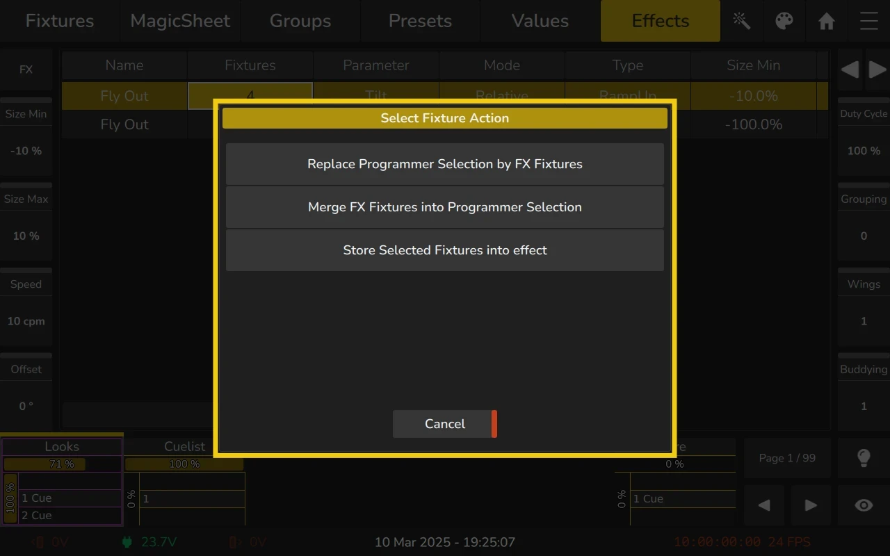
- Double-click or long-press on the Fixtures cell to open the Select Fixture dialog.
- From the dialog, you can:
- Replace Programmer Selection by FX Fixtures:
Replaces the current fixture selection with the fixtures assigned to this effect line. - Merge FX Fixtures into Programmer Selection:
Adds the fixtures of the effect line to the current fixture selection. - Store Selected Fixtures into Effect:
Replaces the fixtures of the effect line with the current fixture selection.
- Replace Programmer Selection by FX Fixtures:
Parameter Column
The Parameter Column displays the fixture function the effect line is assigned to. It is read-only and cannot be changed.
Mode Column
The Mode column displays the current mode of the effect line. You can toggle between Relative and Absolute modes by double-clicking or long-pressing on the cell.
Relative Mode
- Relative Effects apply a mathematical function around the current base value (in the values view or output) of the selected attribute.
- For example, if the Dimmer channel has a base value of 50% and a size of -25% to +25%, the effect will alternate between 25% and 75%. If the base value is 75%, the effect will alternate between 50% and 100%.
Absolute Mode
- Absolute Effects apply a mathematical function from the Size Min value to the Size Max value.
- It’s also possible to use Presets for the Size Min and Size Max values.
- For example, if Size Min is set to 25% and Size Max is set to 25%, the effect will appear "frozen" at 25%. If Size Min is set to 25% and Size Max to 75%, the effect will alternate between 25% and 75%.
Type Column
The EDGE console supports multiple effect curves, as shown here. To change the curve for an effect line, double-tap or long-press the Type cell.
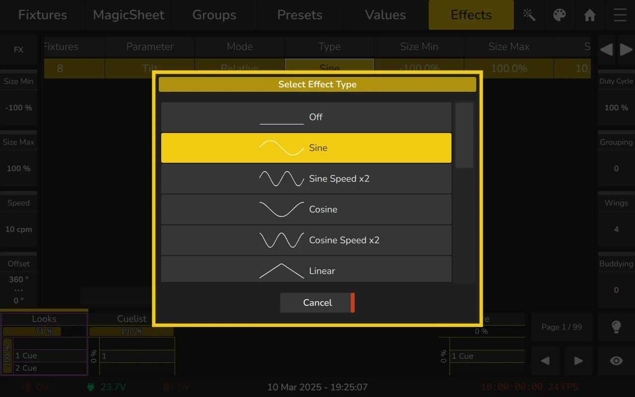
The following effect types are available for selection:
| Icon | Name | Description |
|---|---|---|
| Off Effect | No effect is applied. | |
| Sine Wave | A standard sine wave shape. | |
| Double Speed Sine Wave | A sine wave running at double speed. | |
| Cosine Wave | A standard cosine wave shape. | |
| Double Speed Cosine Wave | A cosine wave running at double speed. | |
| Linear | A straight, linear function. | |
| Ramp Up | Gradual increase from 0% to 100%. | |
| Ramp Down | Gradual decrease from 100% to 0%. | |
| PWM | Pulse Width Modulation. Can be softened at start and end using attack and decay. | |
| Half Sine | A half-cycle of a sine wave. | |
| Random 1 | Generates random values (variation 1). | |
| Random 2 | Generates random values (variation 2). | |
| Impulse | Quick jump from 0% to 100%, then back. | |
| Phase A | Phase-shifted wave shape, variant A. | |
| Phase B | Phase-shifted wave shape, variant B. | |
| Phase C | Phase-shifted wave shape, variant C. |
Size Min Column
The function of the Size Min column depends on the mode set for the effect line.
- If the mode is set to Absolute, you may also choose a Preset for the Size Min value.
- Size Min represents the negative amplitude of the effect. If the mode is Absolute, it is the smallest value of the effect. If it is set to Relative, the output value is the base value minus the effect size.
To change the Size Min value:
- Use the encoders to change the value.
- Long-click or double-click on the Size Min cell.
- To fan the value across multiple fixtures, use the encoders in conjunction with the Fan key on the front panel or within the dialog that opens when you long-click or double-click the cell.
For more details on how the Size Min value behaves based on the mode, see the Mode column description above.

Size Max Column
The function of the Size Max column depends on the mode set for the effect line.
- If the mode is set to Absolute, you may also choose a Preset for the Size Max value.
- Size Max represents the positive amplitude of the effect. If the mode is Absolute, it is the largest value of the effect. If it is set to Relative, the output value is the base value plus the effect size.
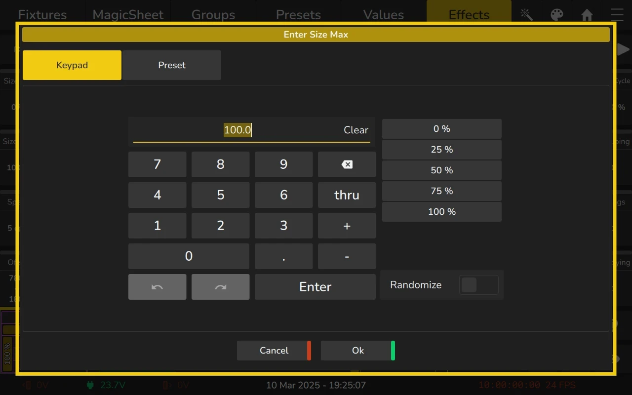
To change the Size Max value:
- Use the encoders to change the value.
- Long-click or double-click on the Size Max cell.
- To fan the value across multiple fixtures, use the encoders in conjunction with the Fan key on the front panel or within the dialog that opens when you long-click or double-click the cell.
For more details on how the Size Max value behaves based on the mode, see the Mode column description above.
Speed Column
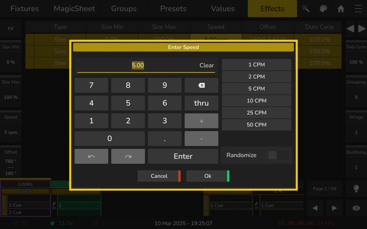
The Speed column defines the speed of the effect in cycles per minute (CPM), which represents the number of times a full effect cycle completes in one minute.
To adjust the Speed value:
- Use the encoders to increase or decrease the speed.
- Double-click or long-click on a Speed cell to open a dialog for precise adjustments.
- To fan the value across multiple fixtures, use the encoders in conjunction with the Fan key on the front panel or within the dialog that opens when you long-click or double-click the cell.
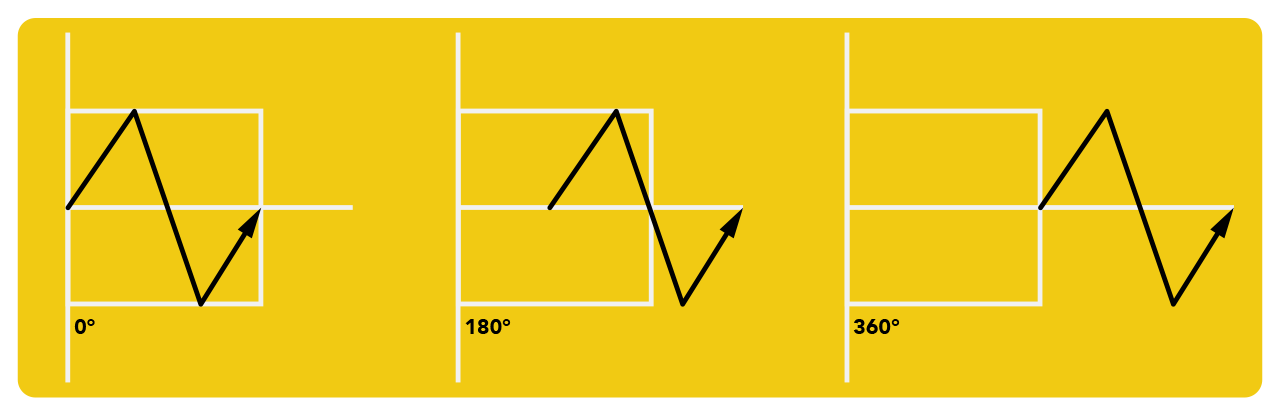
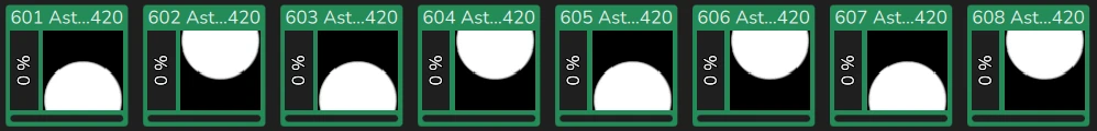
Offset Column
The Offset column defines the starting offset of the effect for each fixture in the effect. The value is entered in degrees (°).
- A range from 0 to 360° fans the offset across all fixtures in the effect row.
- The first fixture starts at 0°, while the others are delayed in sequence, creating a staggered or wave-like effect.
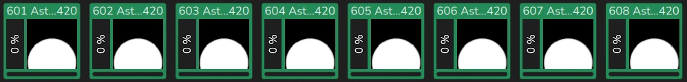
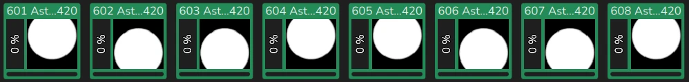
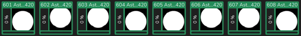
For example, a tilt effect across 8 fixtures without offsets will look like this:
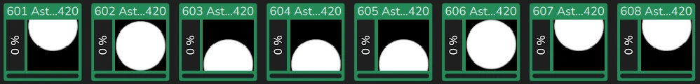
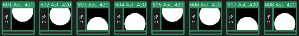
With Offset set to a value of 0 to 360 Degrees, the effect will look like a wave:
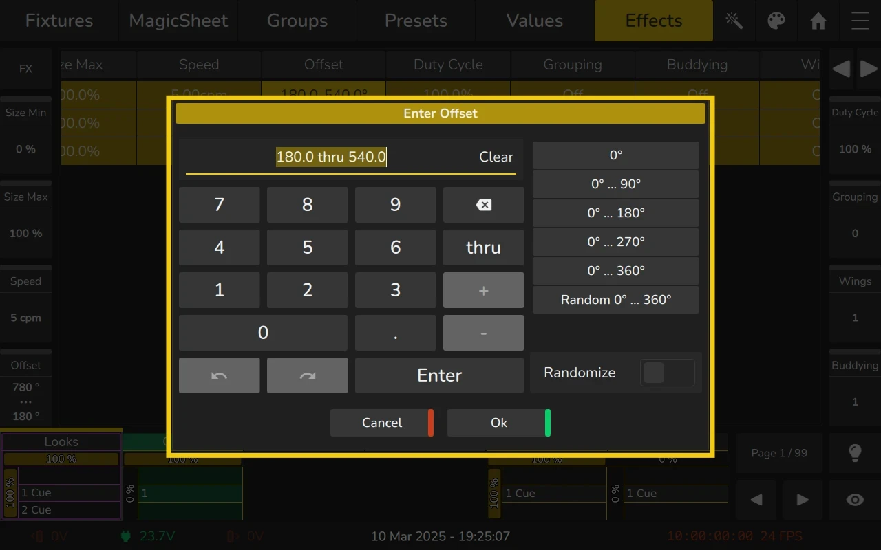
To adjust the Offset value:
- Use the encoders to change the offset.
- Double-click or long-click on an Offset cell to open a dialog for precise adjustments.
- To fan the offset across multiple fixtures, use the encoders in conjunction with the Fan key on the front panel or within the dialog that opens when you long-click or double-click the cell.
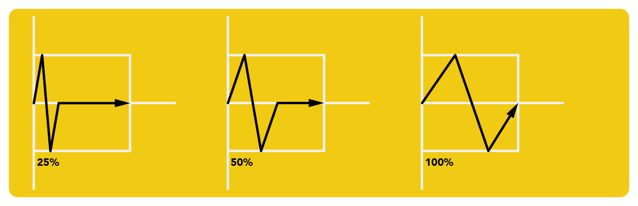
Duty Cycle Column
The Duty Cycle refers to how long the effect curve stays ON compared to the total duration of one cycle. It is expressed as a percentage:
- A higher Duty Cycle means the effect stays ON for a longer period within the cycle.
- A lower Duty Cycle means the effect stays ON for a shorter time within the cycle.
For example:
- 50% Duty Cycle → The effect is active for half of the time and inactive for the other half.
- 25% Duty Cycle → The effect is active for a quarter of the time and inactive for the rest.
- 100% Duty Cycle → The effect is always active.
- 0% Duty Cycle → The effect is always inactive.
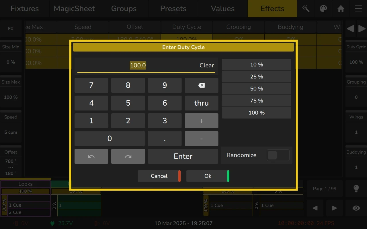
To adjust the Duty Cycle value:
- Use the encoders to adjust the duty cycle.
- Double-click or long-click on the Duty Cycle cell.
- To fan the value across multiple fixtures, use the encoders in conjunction with the Fan key on the front panel or within the dialog that opens when you long-click or double-click the cell.
This attribute is especially useful for creating chases and other rhythmic effects.
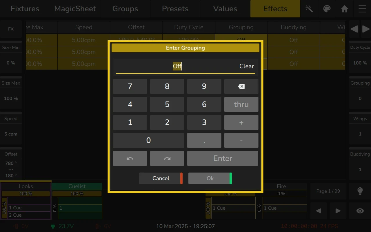
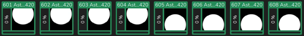
Grouping Column
The Grouping attribute divides the effect into groups, where each group will run the full effect independently. The value specified defines how many fixtures will be in each group.
For example:
- With a Grouping value of 4, the effect will be divided into groups of 4 fixtures.
- Each group of 4 fixtures will run the full effect, and then the same effect will be applied to the next group of 4 fixtures, and so on.
This allows the effect to be repeated across multiple groups of fixtures, giving a structured yet repetitive result.
For example, a tilt wave across 8 fixtures without Grouping will look like this:

With Grouping set to a value of 2, the effect will look like this:
With Grouping set to a value of 4, the effect will look like this:
To adjust the Grouping value:
- Use the encoders to adjust the number of groups..
- Double-click or long-click on the Grouping cell.
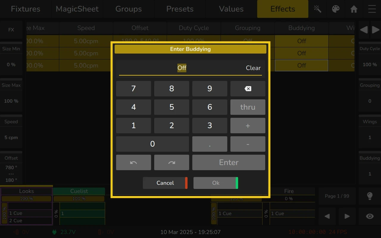
Buddying Column
The Buddying attribute divides all fixtures running the effect into groups, with the value specifying the number of fixtures in each group.
- A Buddying value of 1 means each fixture runs the effect independently.
- A Buddying value of 2 means pairs of fixtures move together.
- A Buddying value of 4 means four fixtures share the same effect timing, and so on.
Example:
A tilt wave effect across 8 fixtures with different buddying settings:
- Buddying = 1 → Each fixture moves independently in sequence.
- Buddying = 2 → The effect is applied to pairs of fixtures.
- Buddying = 4 → The effect is applied to groups of four fixtures at a time.
- Buddying = 8 → All fixtures move together as one group.
For example, a tilt wave across 8 fixtures without Buddying will look like this:

With Buddying set to a value of 2, the effect will look like this:
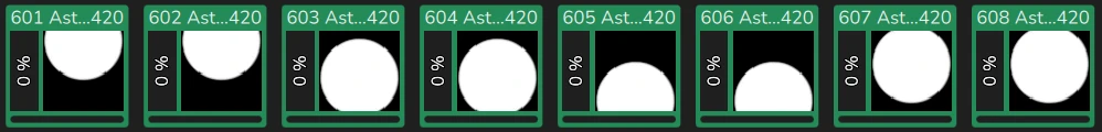
With Buddying set to a value of 4, the effect will look like this:
To adjust the Buddying value:
- Use the encoders to adjust the number of buddies.
- Double-click or long-click on the Buddying cell.
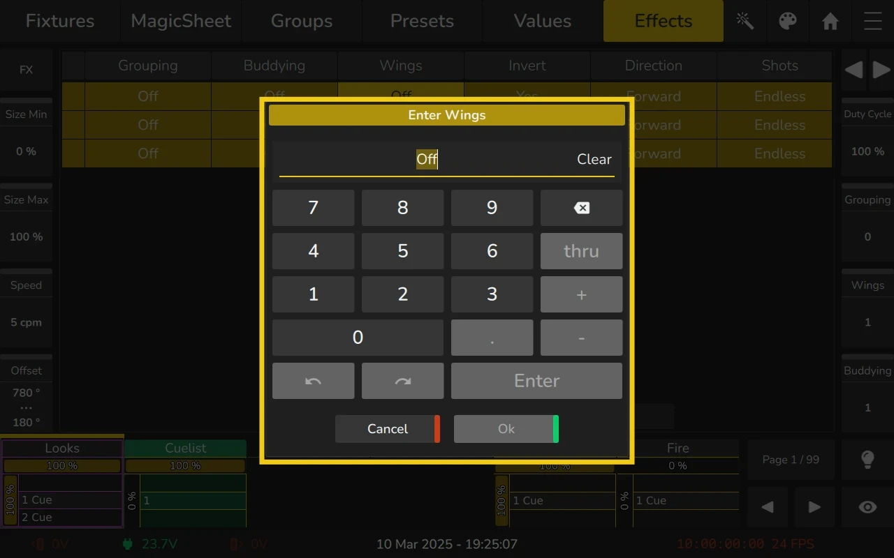
Wings Column
The Wings attribute defines how the effect is mirrored across the fixtures running the effect. When set to a value larger than 1, the effect will be mirrored according to the number specified.
- For example, if Wings = 2, the effect will be mirrored across the fixtures in two parts.
- If the effect runs on the Pan function, the value will also be inverted to create fully symmetric effects, where one side of the effect is the reverse of the other.
For example, a tilt wave across 8 fixtures without Wings will look like this:

With Wings set to a value of 2, the effect will look like this:
With Wings set to a value of 4, the effect will look like this:
To adjust the Wings value:
- Use the encoders to adjust the number of wings.
- Double-click or long-click on the Wings cell.
This attribute is useful for creating symmetrical effects, especially when working with fixtures that need to move in a mirrored fashion.
Invert Column
The Invert column allows you to quickly swap the Minimum and Maximum size values for the effect. This is useful for reversing the direction of the effect without manually adjusting the size parameters.
To adjust the Invert value:
- Double-click or long-click on the Invert cell.
This will automatically invert the size values, making the effect run in the opposite direction.
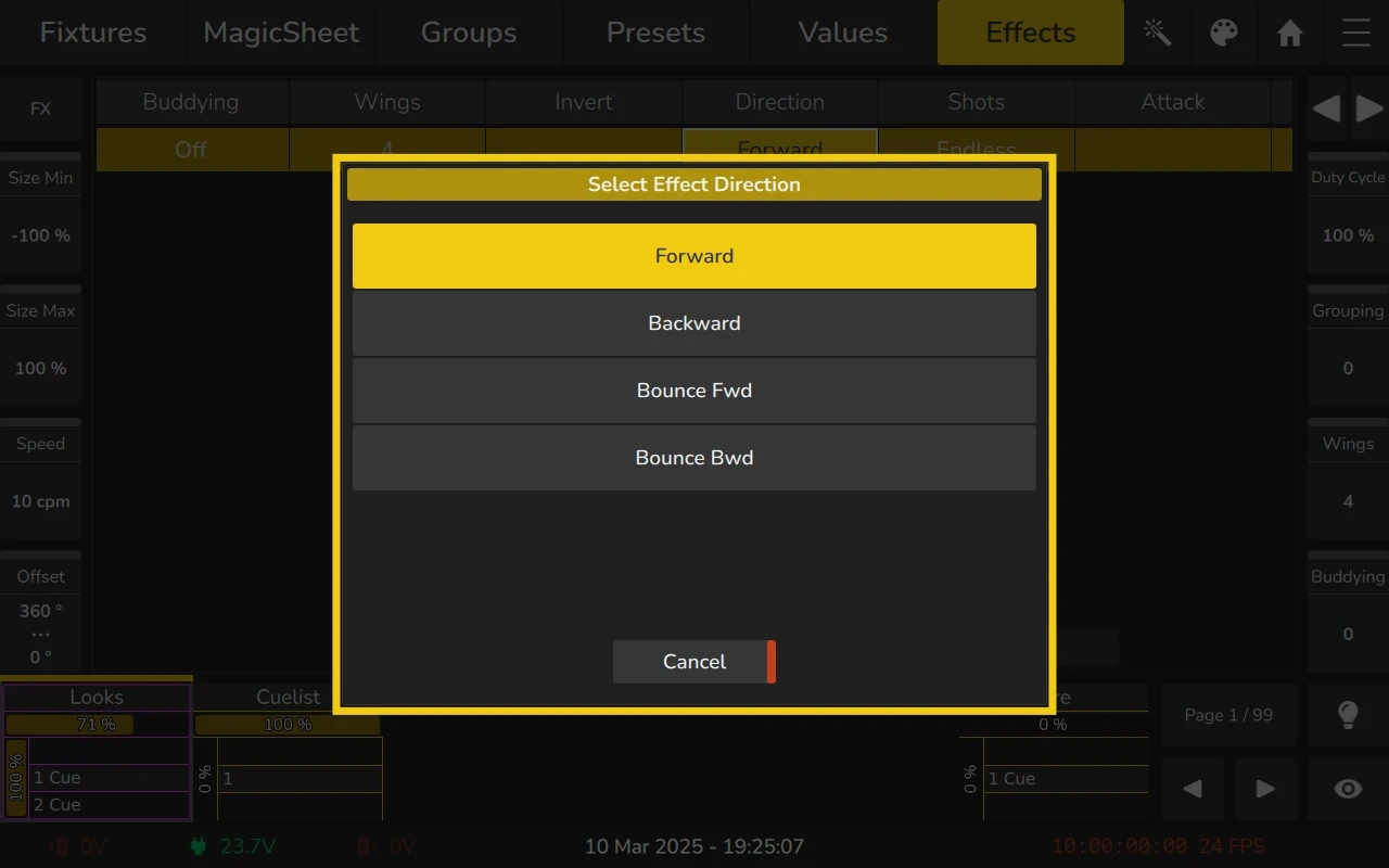
Direction Column
The Direction column displays the direction in which the effect will run. You can change the direction by selecting an option from the Set Effect Direction Dialog.
To adjust the Direction value:
- Double-click or long-click on the Direction cell, and choose the desired option.
The following directions can be selected:
- Forward: The effect will run in the forward direction.
- Backward: The effect will run in the reverse direction.
- Bounce Fwd: The effect will run forward and then bounce backward after reaching the last fixture.
- Bounce Bwd: The effect will run backward and then bounce forward after reaching the last fixture.
This attribute allows you to control how the effect moves across the fixtures in a playback.
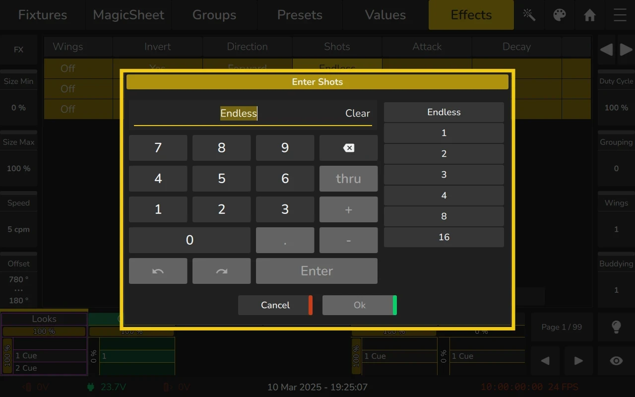
Shots Column
The Shots column defines how many times an effect should be run before it “self-terminates”.
- If set to Endless (0), the effect will run indefinitely until it is stopped by another effect or the Playback/Scene is switched off.
- If set to 1, the effect will run once and then stop.
- Any other value defines the number of cycles the effect will complete before terminating.
To reset the effect to run endlessly, simply enter 0 in the Shots cell.
To adjust the Shots value:
- Double-click or long-click on the Shots cell.
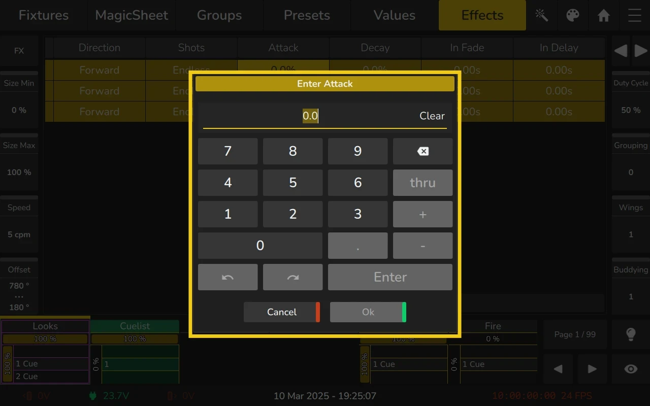
Attack Column
The Attack column defines how quickly the effect ramps up to full intensity from the start. It is measured in percentage and controls the duration over which the effect transitions from "off" to its full value.
A higher Attack value means a slower ramp-up, resulting in a more gradual transition to full intensity. A lower Attack value means the effect reaches full intensity more quickly.
This attribute is only supported for PWM (Pulse Width Modulation) effects.
To adjust the Attack value:
- Double-click or long-click on the Attack cell.
This attribute is useful for controlling the smoothness of the effect’s start, allowing for soft fades or more abrupt transitions.
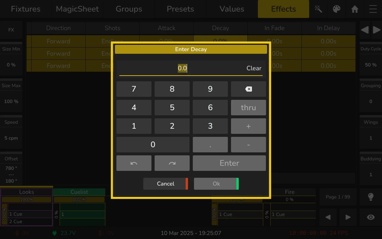
Decay Column
The Decay column defines how quickly the effect fades out from full intensity to "off" once it has reached its peak value. It is measured in percentage and controls the duration over which the effect decreases in intensity.
A higher Decay value means a slower fade-out, resulting in a more gradual decrease in intensity. A lower Decay value means the effect fades out more quickly.
This attribute is only supported for PWM (Pulse Width Modulation) effects.
To adjust the Decay value:
- Double-click or long-click on the Decay cell.
This attribute is useful for controlling the smoothness of the effect’s fade-out, allowing for soft releases or more abrupt endings.
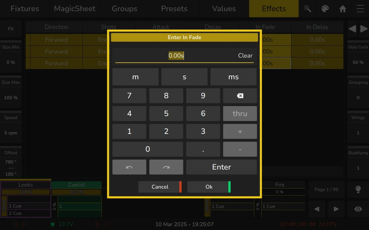
In-Fade Column
The In-Fade column defines how quickly the effect fades in from zero intensity to its starting value. It is measured in percentage and controls the duration over which the effect transitions from "off" to its initial intensity.
A higher In-Fade value means a slower fade-in, resulting in a more gradual increase in intensity. A lower In-Fade value means the effect reaches its starting intensity more quickly.
To adjust the In-Fade value:
- Double-click or long-click on the In-Fade cell.
This attribute is useful for controlling how smoothly the effect begins, allowing for softer starts or more immediate intensity.
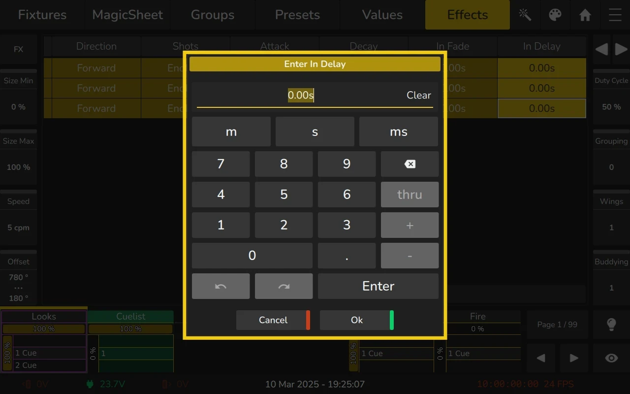
In-Delay Column
The In-Delay column defines how long the effect waits before starting its transition to full intensity. It is measured in percentage and controls the delay before the effect begins.
A higher In-Delay value means the effect will wait longer before starting, resulting in a delayed onset. A lower In-Delay value means the effect starts sooner.
To adjust the In-Delay value:
- Double-click or long-click on the In-Delay cell.
This attribute is useful for introducing a delay before an effect begins, allowing for timing adjustments and creating more complex, rhythmic effects.